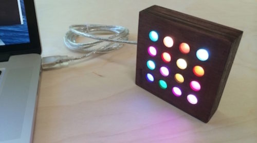
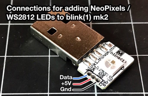
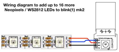
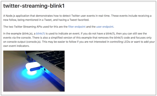
Now you can more easily add "Neopixel" WS2812 LED strips to your blink(1) mk2 with the "blink1 LED strip adapter". This is a simple PCB that breaks out the tiny 3-pin socket on the blink(1) board to a standard 0.1" spacing for LED strips.
The design is completely open source and you can get your own made for a few bucks by going to the blink1-ws2812-adapter page on OSHPark.


Below are some photos showing how you can solder one up to a blink(1) mk2 circuit board. It assumes you've already taken the board out of the enclosure as described in a previous post.
Gathering parts

Here's all the parts you need:
- blink(1) mk2
- blink1-ws2812-adapter board
- 8-pin stacky header or equivalent
The tools you will need are the standard kit for electronics work:
- soldering iron & solder
- needle nose pliers
- diagonal cutters
- locking tweezers or small clamp
Aligning the boards
After removing the blink(1) circuit board from its enclosure, we need to get three sturdy "wires" to go from the blink(1) to the adapter board. I like using the pins of a "stacky header". To remove them, just pull them out with needle nose pliers.

Then, line up the blink(1) and the adapter board and insert the three pins. It's handy to have a clamp or auto-closing tweezers to hold the two boards together while you're doing this.

Soldering the boards together
And now just solder from the top and from the bottom, taking care not to bridge solder across the pins.
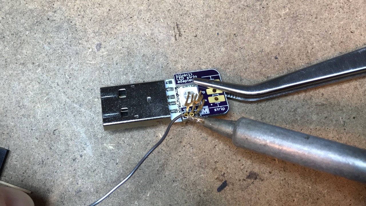

Finally trim the pins/wires close to the boards. Trim one lead at a time to prevent possible shorting. And do a quick continuity check afterwards to make sure nothing in shorted.


Adding the LED strip header socket (optional)
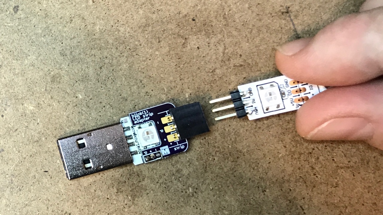
You can also solder in a female header socket to make it easy to add and remove LED strips. Using the remaining part of the "stacky header", pull out another pin and cut the header to leave you with a 3-pin header socket. Insert that into the adapter board, solder it down, and trim the excess leads.


Plugging in LED strips
Now you can plug in strips. If you solder a 3-pin header onto your strips, you can plug them in straight away! Be sure your strip matches the order of "GND-DAT-5V" for the connections. Most strips have this, but some don't. Otherwise, you can solder wires onto the strips and them plug them into the socket.

Controlling the LEDs
With the 'blink1-tool' command-line program (available from the blink1 project releases page), you can use the 'ledn' parameter to set which LED you'd like to control. When 'ledn' is zero, all LEDs are changed. LED 1 and 2 are the top and bottom LEDs of the blink(1), respectively.
blink1-tool --ledn 5 --rgb '#FF00FF' // turn 5th LED purple
blink1-tool --led 16 --random=100 -m 10 -t 10 // party mode!


